Showing posts with label timer. Show all posts
Showing posts with label timer. Show all posts
Monday, May 13, 2013
Long delay Timer
This timer was designed mainly to switch off a portable radio after some time: in this way, one can fall asleep on the sand or on a hammock, resting assured that the receiver will switch off automatically after some time, saving battery costs.
 Parts: R1______________10M 1/4W Resistor R2_______________4K7 1/4W Resistor R3_______________1K 1/4W Resistor (Optional, see Text) C1_____________220µF 25V Electrolytic capacitor D1______________LED any type and color (Optional, see Text) D2___________1N4148 75V 150mA Diode (Optional, see Text) IC1____________4011 Quad 2 Input NAND Gate CMos IC (See Notes) Q1____________BC337 45V 800mA NPN Transistor P1,P2__________SPST Pushbuttons RL1___________Relay with SPDT 2A @ 230V switch (Optional, see Text) Coil Voltage 12V - Coil resistance 200-300 Ohm Circuit operation: R1 and C1 provide a very long time constant. When P2 is momentarily closed, C1 discharges and the near zero voltage at its positive lead is applied to the high impedance inputs of the four gates of IC1 wired in parallel. The four paralleled gate outputs of the IC go therefore to the high state and the battery voltage is available at Q1 Emitter. When P2 is released, C1 starts charging slowly through R1 and when the voltage at its positive lead has reached about half the battery voltage, the IC gate outputs fall to zero, stopping Q1.
This transistor can directly drive a portable radio receiver or different devices drawing a current up to about 250mA. Connecting a Relay across the Emitter of Q1 and negative ground, devices requiring much higher voltage and current operation can be driven through its contacts. Pushing on P2 for 1 to 5 seconds, the circuit starts and then will switch off after about 35 minutes. This time delay can be varied by changing R1 and/or C1 values. P1 will stop the timer if required. LED D1 is optional and can be useful to signal relay operation when the load is placed far from the timer. Notes: * A 4011 Quad 2 Input NAND Gate was used for IC1, but many other CMos gates or inverter arrays can be used in its place, e.g. 4001, 4002, 4025, 4012, 4023, 4049, 4069.
With these devices, all inputs must be tied together and also all outputs, as shown in the Circuit diagram. * The operating voltage of this circuit should lie in the 6 - 12V range.
Read More..
Parts: R1______________10M 1/4W Resistor R2_______________4K7 1/4W Resistor R3_______________1K 1/4W Resistor (Optional, see Text) C1_____________220µF 25V Electrolytic capacitor D1______________LED any type and color (Optional, see Text) D2___________1N4148 75V 150mA Diode (Optional, see Text) IC1____________4011 Quad 2 Input NAND Gate CMos IC (See Notes) Q1____________BC337 45V 800mA NPN Transistor P1,P2__________SPST Pushbuttons RL1___________Relay with SPDT 2A @ 230V switch (Optional, see Text) Coil Voltage 12V - Coil resistance 200-300 Ohm Circuit operation: R1 and C1 provide a very long time constant. When P2 is momentarily closed, C1 discharges and the near zero voltage at its positive lead is applied to the high impedance inputs of the four gates of IC1 wired in parallel. The four paralleled gate outputs of the IC go therefore to the high state and the battery voltage is available at Q1 Emitter. When P2 is released, C1 starts charging slowly through R1 and when the voltage at its positive lead has reached about half the battery voltage, the IC gate outputs fall to zero, stopping Q1. This transistor can directly drive a portable radio receiver or different devices drawing a current up to about 250mA. Connecting a Relay across the Emitter of Q1 and negative ground, devices requiring much higher voltage and current operation can be driven through its contacts. Pushing on P2 for 1 to 5 seconds, the circuit starts and then will switch off after about 35 minutes. This time delay can be varied by changing R1 and/or C1 values. P1 will stop the timer if required. LED D1 is optional and can be useful to signal relay operation when the load is placed far from the timer. Notes: * A 4011 Quad 2 Input NAND Gate was used for IC1, but many other CMos gates or inverter arrays can be used in its place, e.g. 4001, 4002, 4025, 4012, 4023, 4049, 4069.
With these devices, all inputs must be tied together and also all outputs, as shown in the Circuit diagram. * The operating voltage of this circuit should lie in the 6 - 12V range.

Monday, April 8, 2013
Touch Free Timer Switch
This type of infrared proximity circuit is widely used as an electric switch where physical contact is not desired for hygiene purpose. For example, we commonly see use of infrared proximity sensors on public drinking fountains and in public washrooms. The simple circuit presented here can be operated by moving your hand in front of it. This is achieved by detecting the infrared light reflected by your hand onto a receiver device.
Fig. 1: Touch-Free Timer Switch Circuit diagram :

Fig. 1 shows the circuit of the touch-free timer switch. It has two sections: transmitter and receiver. The IR transmitter is built around timer LMC555 (IC1), which is wired as an astable multivibrator. The multivibrator produces 38kHz pulses (at low duty cycle) that drive an infrared LED (LED1). This frequency can be tuned using a 10-kilo-ohm preset (VR1). A 220-ohm series resistor (R3) ensures that the current consumption of the IR transmitter is not out of arrangement.
The receiver section is built around IR receiver module TSOP1738 (IRX1), timer LMC555 (IC2) and a few discrete components. The TSOP1738 is an integrated miniaturised receiver for infrared remote control systems. Everything required for IR signal processing, including the PIN diode and preamplifier, are assembled on a lead frame and the epoxy package is designed as an IR filter.
When a short IR burst is received by IRX1 (as you wave your hand in front of the switch), the demodulated pulses are fed to the trigger input (pin 2) of the second LMC555 (IC2). This, in turn, triggers the monostable wired around IC2 and its output pin 3 goes high for a period determined by the 2.2-mega-ohm potentiometer and capacitor C5. This turns off the standby indicator (LED1) and transistor T1 conducts to drive the 5V relay (RL1). LED1 enables you to locate the switch in the dark. AC mains supply to the load to be switched-on is routed through the pole and normally-opened contacts of RL1 as shown in the diagram. The circuit works off regulated 5V DC.
Fig. 2: Pin configurations of TSOP1738, IR LED and BC547

Fig. 2 shows the pin configurations of TSOP1738, IR LED1 and transistor BC547. Assemble the circuit on a general-purpose PCB and enclose in a small plastic cabinet. Fit IR LED1 with a reflecting hood at a recessed position on the front panel of the enclosure. The dome-shaped face of the TSOP1738 should stick out from the front panel. Fit the time-control potentiometer (VR2) in an appropriate position. Finally, fit the standby indicator LED1 inside a suitable LED holder such that it slightly protrudes from the front panel. To prevent unwanted reflection of the IR beam, the finished unit should be mounted such that it does not face a nearby wall.
Fig. 3: Suggested enclosure

Using high-precision linear potentiometer VR2 and capacitor C5 (100µF), the time length can be set from nearly 1 second to 120 seconds. Attach a small paper dial on the front panel of the enclosure and mark various positions of the control knob of VR2 as shown in Fig. 3. The accuracy of the timer depends mainly upon the quality (and value) of timing capacitor C5. In practice, most electrolytic capacitors are rated on the basis of minimum guaranteed value and the real value may be higher.
Source : http://www.ecircuitslab.com/2012/08/touch-free-timer-switch-circuit.html
Saturday, April 6, 2013
PWM controller with 555 timer chip
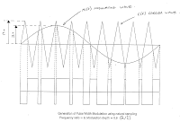
IC Timer 555 has a basic PWM controller with pulse width control feature 0 .. 100% which is controlled using the R1, at the time of controlling the oscillator frequency relatively stabi so it may be used to build the Simple PWM controller.
Frequency of Simple PWM controller 555 depending on the value of R1 and C1, values shown R1 and C1 will form the output with a frequency of 170 to 200 Hz. Diode-diode used in the Simple PWM controller With this 555 can use a 1N4148.
R2, R3 and C3 form a giver triger circuit beginning at the reset IC 555 for 2 seconds. If you want to use a series of Simple PWM controller 555 with the V + not +12 V, it does not matter to raise tilapia R2 where (V + * R2) / (R2 + R3) is about 2, because it limits the signal level reset is 0.5 .. 1V. If you do not do that, then signal the kickstart to get too close to the limit reset signal reception.
 |
| PWM controller circuit |
Q output of 555 on the Simple PWM controller circuit 555 is used for driver PWM pulse, so that the discharge pin is used for transistor output driver instead. This is an open collector output, and is used as an active signal is low, so it can work. D3 protects the output transistor of the load induction. You may replace any suitable transistors for Q1, BD140 is 1.5 amps.
C4 and C5 is the power decoupling capacitor for the IC 555 on the Simple PWM controller circuit 555, which produce relatively large level of push-pull output stage.
Subscribe to:
Posts (Atom)


