Monday, April 1, 2013
Infrared Remote control transmitters
I need not tell you much, what is the infra red remote control. Because you have known as well. so I recommend circuits 2 types, as appropriate.
- The first is simple circuits. Infrared light from a set to a set to work immediately.
- Then another circuits, is designed to have wider applications. Can be set program that will be must have a beam of infrared light to circuits few times to work.
Which both need to have the good Infrared Remote control circuit, before.
The infrared remote control transmitter circuit.
Usually, when input voltage to the infrared diode. Will be have the beam infrared light which can be seen with the naked eye out
-But in real applications. We need to enter the signal pulse with a frequency of about 5kHz, to the infrared diode, for eliminate the various interference. And reduce the power supplied to the diode.
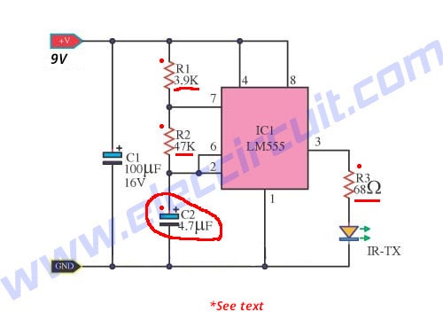
In the first circuits, to be a simple infrared transmitter with IC-555 timer to an oscillator generator at frequency of 5kHz, that is set with R1,R2 and C2. The output signal will have signal period on-off 1:1
The resistor R3 is used to limit current flow through the infra red diode under 50mA.

If you want the infrared transmitter that has the signal strength is very high. You can be done by adding the output transistors. Enable With the infrared diodes up to three tubes.

Be seen from the circuit, IC 555 use to function frequency generator is 5000Hz as well. The frequency of the circuit is determined by the VR1, R1, R2 and C1, we can customize the frequency by adjusting VR1.
Output of IC is supplied to the transistor Q1-BD137 to drive infrared diodes with high current to 100mA. Risisetars R3 in the circuit should not be less than 3.9 ohm as it may cause damage to TR1. R4 and LED1 to indicate that the voltage supply to the circuits.
Infrared transmitters by LM3909
This is an infrared transmitters signal circuit that is small size and using a power supply 1.5V only. by main electronic part are two the LM3909 (a LED Flasher Oscillator IC) Normally, we tend to put it to use as a simple flashing light circuit. Using a 1.5V low power supply, it’s working now, Easier to use transistors. The high frequency, it is very simple, just change the device to high frequency only. C1 and R1 is lower the higher frequency.
Labels:
control,
infrared,
remote,
transmitters
