Showing posts with label 12. Show all posts
Showing posts with label 12. Show all posts
Thursday, September 5, 2013
LED 12 Volt Lead Acid Battery Meter Circuit
In the circuit below, a quad voltage comparator (LM339) is used as a simple bar graph meter to indicate the charge condition of a 12 volt, lead acid battery. A 5 volt reference voltage is connected to each of the (+) inputs of the four comparators and the (-) inputs are connected to successive points along a voltage divider. The LEDs will illuminate when the voltage at the negative (-) input exceeds the reference voltage. Calibration can be done by adjusting the 2K potentiometer so that all four LEDs illuminate when the battery voltage is 12.7 volts, indicating full charge with no load on the battery. At 11.7 volts, the LEDs should be off indicating a dead battery. Each LED represents an approximate 25% change in charge condition or 300 millivolts, so that 3 LEDs indicate 75%, 2 LEDs indicate 50%, etc. The actual voltages will depend on temperature conditions and battery type, wet cell, gel cell etc. 
Source http://www.bowdenshobbycircuits.info/
Circuit Diagram

Monday, April 8, 2013
12 Volt to 32 Volt CT converter DC to DC

Kit that can change the normal 12v dc voltage from a car battery, battery bike 12V motor. With the current 7A. so this circuit is very suitable for power car amplifiers and sound systems that use simple 12V battery.
Kit converter is also equipped with inputs "SEND" to activate the circuit and also send this interchangeable inputs is connected to the Tape / cd / dvd player of your car. And input "send" is if the non-connected with an output of "send" player car you then connect it to +12 hrs on v from the battery / batteries The series is already in the test kit and has been functioning normally.
Kit converter is also equipped with inputs "SEND" to activate the circuit and also send this interchangeable inputs is connected to the Tape / cd / dvd player of your car. And input "send" is if the non-connected with an output of "send" player car you then connect it to +12 hrs on v from the battery / batteries The series is already in the test kit and has been functioning normally.
Wednesday, April 3, 2013
6 12 Volt Adjustable Power Supply Circuit

Power Supply has an adjustable output with a range of 6-12 VDC. The part that serves as a power regulator is Q1 TIP31. Then the controller output voltage is a voltage divider composed of R3, R4, VR1 and R2 provide bias to the base of Q2 to Q1 mengentrol power regulator. In a series of power supply is mounted 5.1 V zener diode which serves to make the minimum limit the output voltage with Q2.
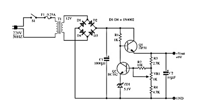 |
| Adjustable Power Supply with transistor circuit |
Power Supply With transistor circuit is quite simple and can be made with the PCB holes, so for those who want to try to directly mempraktikannya. May the power supply circuit can be useful for readers, especially for friends who need a power supply circuit with the regulator transistor.
Subscribe to:
Posts (Atom)


