Showing posts with label battery. Show all posts
Showing posts with label battery. Show all posts
Friday, December 27, 2013
Under voltage Indicator for Battery Equipment Circuit Diagram
This is the simple Under voltage Indicator for Battery Equipment Circuit Diagram. Due to the low duty cycle of flashing LED, the average current drain is 1 mA or less. The NE555 will trigger the LED on when the monitored voltage falls to 12 volts.The ratio of Rl to R2 only needs to he changed if it is desired to change the voltage point at which the LED is triggered.
Under voltage Indicator for Battery Equipment Circuit Diagram

Thursday, December 19, 2013
Battery Charging Indicator
The Over-the-Top type of operational amplifier is ideal for use as a current sense for battery charger applications. The design described here can be used with chargers for rechargeable batteries (Lead/acid or NiCd etc). The 5V operating supply for the circuit is derived from the battery on charge. The circuit uses a sense resistor R8 to determine the value of current flowing in or out of the battery.
An LED output shows whether the battery is charging or discharging and an analogue output displays the battery charge or discharge current. The circuit can also be altered to shown different ranges of charging current to cater for higher capacity cells. IC1a and IC1b together with T1 and T2 form two current sources, which produce a voltage across R5. The voltage across R5 is proportional to the current through resistors R8 and R1 (for IC1a) or R8-R3 (for IC1b).
The current source formed by IC1a and T1 is active when the batteries are discharging and IC1b and T2 is active when the batteries are being charged. In each case the inactive opamp will have 0V at its output and the corresponding transistor will be switched off. IC1d amplifies the voltage across R5, which is proportional to the sense current. The component values given in the diagram produce an amplification factor or 10.
A sense current of 0.1 A will produce an output voltage of +1 V. The supply voltage to the circuit is +5 V so this will be the maximum value that the output can achieve. This corresponds to a maximum charge/discharge current of 0.5 A To display currents from 0 to 5.0 A, resistor R7 can be omitted to give IC1d a voltage gain of 1. Higher currents can be displayed by using a lower value of sense resistor R8. A DVM or analogue meter can be used at Vout to give a display of the charge/discharge current.
The constant current sources can only function correctly when the supply to the voltage regulator circuit (UBatt. e.g. 6V or 12V) is greater than the operating voltage of the opamps (+5 V). The supply voltage to the LT1639 can be in the range of +3 V and +44V and voltages up to 40V over the supply voltage are acceptable at the inputs to the opamp. IC1c controls the charging/discharging LED output. The inputs to this opamp are connected to the outputs of the current source opamps and its output goes high when the battery is being charged and low when it is discharging.
Read More..
 |
| Battery Charging Indicator Circuit Diagram |
An LED output shows whether the battery is charging or discharging and an analogue output displays the battery charge or discharge current. The circuit can also be altered to shown different ranges of charging current to cater for higher capacity cells. IC1a and IC1b together with T1 and T2 form two current sources, which produce a voltage across R5. The voltage across R5 is proportional to the current through resistors R8 and R1 (for IC1a) or R8-R3 (for IC1b).
The current source formed by IC1a and T1 is active when the batteries are discharging and IC1b and T2 is active when the batteries are being charged. In each case the inactive opamp will have 0V at its output and the corresponding transistor will be switched off. IC1d amplifies the voltage across R5, which is proportional to the sense current. The component values given in the diagram produce an amplification factor or 10.
A sense current of 0.1 A will produce an output voltage of +1 V. The supply voltage to the circuit is +5 V so this will be the maximum value that the output can achieve. This corresponds to a maximum charge/discharge current of 0.5 A To display currents from 0 to 5.0 A, resistor R7 can be omitted to give IC1d a voltage gain of 1. Higher currents can be displayed by using a lower value of sense resistor R8. A DVM or analogue meter can be used at Vout to give a display of the charge/discharge current.
The constant current sources can only function correctly when the supply to the voltage regulator circuit (UBatt. e.g. 6V or 12V) is greater than the operating voltage of the opamps (+5 V). The supply voltage to the LT1639 can be in the range of +3 V and +44V and voltages up to 40V over the supply voltage are acceptable at the inputs to the opamp. IC1c controls the charging/discharging LED output. The inputs to this opamp are connected to the outputs of the current source opamps and its output goes high when the battery is being charged and low when it is discharging.
- Source
- Elektor
Wednesday, October 9, 2013
Bike Battery Charger
This simple circuit allows a 12V battery pack to be charged via a bike generator. The generator is rated at 3W and with this voltage multiplier circuit provides about 200mA at about 15km/h. A 12V system was chosen because it allows the use of a car horn (get noticed)! Two 6V 3W globes in series provides adequate lighting and they last more than six months
Read More..
Thursday, September 5, 2013
LED 12 Volt Lead Acid Battery Meter Circuit
In the circuit below, a quad voltage comparator (LM339) is used as a simple bar graph meter to indicate the charge condition of a 12 volt, lead acid battery. A 5 volt reference voltage is connected to each of the (+) inputs of the four comparators and the (-) inputs are connected to successive points along a voltage divider. The LEDs will illuminate when the voltage at the negative (-) input exceeds the reference voltage. Calibration can be done by adjusting the 2K potentiometer so that all four LEDs illuminate when the battery voltage is 12.7 volts, indicating full charge with no load on the battery. At 11.7 volts, the LEDs should be off indicating a dead battery. Each LED represents an approximate 25% change in charge condition or 300 millivolts, so that 3 LEDs indicate 75%, 2 LEDs indicate 50%, etc. The actual voltages will depend on temperature conditions and battery type, wet cell, gel cell etc.
Source http://www.bowdenshobbycircuits.info/
Circuit Diagram
Tuesday, April 9, 2013
7 2V Battery Replacement Power Supply For Camcorders
This circuit lets an external 12V SLA battery power a camcorder which normally has an inbuilt 7.2V battery. Such batteries can now be very difficult or expensive to obtain for earlier model camcorders. In essence, the circuit is a standard LM317 adjustable regulator with resistors R1 & R2 set to provide 7.2V (depending on the accuracy of the 1.25V internal reference). If the resulting output voltage is low, it can be increased by reducing the 130 resistor and vice versa. The circuit can be assembled on to the Eliminator PC board or the simple DC power supply PC board. The regulator should be fitted with a flag heatsink. Note that the circuit should be disconnected from the battery when not in use, otherwise its quiescent current (from the LED and regulator) will flatten the SLA battery.
Circuit diagram:
Read More..
Circuit diagram:

7.2V Battery Replacement Circuit Diagram For Camcorders
Labels:
2v,
7,
battery,
camcorders,
for,
power,
replacement,
supply
Saturday, April 6, 2013
Making a Solar Energy Powered an iPhone Battery Charger
The project was termed as Mighty Minty Boost as it was developed to function as iPod/iPhone charger with solar power. Aside from being small, it has a large battery capacity of 3.7V at 2000mAh and it accepts input power from 3.7V to 7V. As shown in the images below, it can become a compact USB power supply when the solar cell is removed after charging. The Velcro is used to secure the Mighty Minty Boost inside a backpack or messenger bag after unplugging the solar cell.
For faster charging, a larger solar cell can be attached to the bag. Enough power can be generated to fully charge an iPhone in about 5.5 hours and an iPod Touch in 4 hours using a slightly larger solar cell with 6V at 250mAh. The charger will automatically switch to trickle charging when the cell reaches full charge. The charging current is limited to 100mA when charging using the mini USB port and the charging is limited to 280mA when charging using the barrel plug jack
For faster charging, a larger solar cell can be attached to the bag. Enough power can be generated to fully charge an iPhone in about 5.5 hours and an iPod Touch in 4 hours using a slightly larger solar cell with 6V at 250mAh. The charger will automatically switch to trickle charging when the cell reaches full charge. The charging current is limited to 100mA when charging using the mini USB port and the charging is limited to 280mA when charging using the barrel plug jack

.
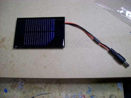
The materials needed to build the charger include a small solar cell, Lithium Polymer battery charger, minty boost kit, adhesive backed Velcro, Altoids tin, connector/wire, and small double adhesive squares as shown in the images below. An input power that ranges from 3.7V to 7V maximum can be accepted by the single cell Lithium Polymer. In bright sunlight, the solar cell maxes out at approximately 5V at 100mA. A larger solar cell with 6V at 250mA can be used for faster charging.

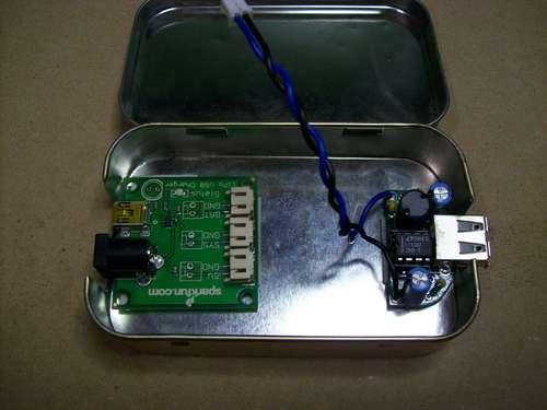
The images below show the assembly of minty boost kit where a JST connector is soldered to the minty boost PCB instead of connecting the battery holder in the kit. The minty boost circuit is allowed to connect to the Lithium Polymer battery charger circuit with this tiny connector. The minty boost is tested by connecting the battery pack and the charger circuit, the Lithium Polymer battery connects to the connector marked GND on the charger board and the minty boost connects to the connector marked SYS.

To fit the charger, a notch is cut out of the other side of the Altoids tin and used double sided adhesive to secure the charging circuit to the bottom of the Altoids as shown below. The bottom of either one of the circuit boards should not touch the bottom of the Altoids tin while reconnecting the minty boost PCB and the battery to the charging circuit.

Connecting or adding the solar cell can be done in different ways. Shortening the connector leads and plugging the barrel plug into the barrel jack on the charging circuit is one way. The other method is using another JST connector to replace the connector and plugging it into the third connector marked 5V on the charging circuit. Since there is no bog barrel plug sticking out of the side of the tin, using the second method is cleaner.
As shown in the photos below, some 2” Velcro was used to attach the solar cell to the top of the Altoids. To help protect the battery, a layer of clear packing tape was used for wrapping. N top of the two circuit boards, the battery pack is then set down. A red LED on the charger board will light up when the Mighty Minty Boost is set out in the bright sun. The iPod/iPhone/USB powered device can be connected once it is fully charged.

Subscribe to:
Posts (Atom)


