Showing posts with label power. Show all posts
Showing posts with label power. Show all posts
Friday, December 20, 2013
Build a Bridge Circuit Diagram With One Power Supply
This is simple Bridge Circuit Diagram With One Power Supply. For systems with only one power supply, two op amps act as instrumentation and buffer amps. The OPA111 AM buffers the reference mode of the bridge and applies that voltage to the instrumentation amps ref terminal. Output is taken between the amplifier outputs to exclude the fixed output offset.
The additional op amp creates a bridge error of 2, where IB=bias current of op amp and R is the resistance of one leg of the bridge.
Bridge Circuit Diagram With One Power Supply


Tuesday, October 8, 2013
POWER CONVERTER TOPOLOGY ELECTRONIC CIRCUIT DIAGRAM

POWER CONVERTER TOPOLOGY and MOSFET SELECTION FOR 48-V TELECOM APLICATIONS ELECTRONIC CIRCUIT DIAGRAM
Output voltages are frequently 5V and below with 3.3V probably the most common requirement, and 2.5V gaining in popularity. If a processor is on the card, voltages as low as 1.3V are not unlikely. One common approach is to regulate a distributed power bus, say the 5V rail, and then use non-isolated DC/DC converters to generate lower voltages. With the tendency away from 5V, the 3.3V rail is beginning to serve as the distributed bus, although, from the power supply designer’s perspective, this is not the most of desirable situations.
Fairchild has recently introduced a family of high voltage MOSFETs ranging from 80- to 200-V drain voltage specifications. This application note will provide information helpful in the proper selection of FETs for primary side switches – available in various types of 48V power converters.
Monday, September 23, 2013
zBot 10 A Power Stage for DC Motor
If you look at the chassis of the zBot vehicle1, you’ll find two parts requiring intelligent control: the steering servo and the DC motor. The so called H-bridge is the normal circuit for electronic control of revolution speed and direction. The DC motor of a Tamiya car is powerful enough to propel zBot at up to 20 miles per hour.

The motor then consumes more than 10 A, so we choose high-current power MOSFETs for the driver stage. There are lots of different devices to choose from. The MOSFET we require has to supply the maximum motor current and, importantly, it has to be switched with gate voltages of about 5 V. In this case, the microcontroller switches the power stage (‘low side’) directly. For high side driving level shifters are necessary. The schematic of the H-bridge power stage shows a few inverters, NAND gates and two tri-stateable drivers. These logic functions are very important as the easier way, i.e.., directly controlling all four MOSFET has a fatal disadvantage.

In case of a software crash it could happen that two ore more MOSFETs are switched on incor-rectly for exam-ple, T4 and T7. In that case, the current through the transistors is limited by the internal resistors of the MOSFETs (about 10 mO) only. Such a fatal error would destroy the MOSFETs. The logic functions configured here effectively avoid illegal states.To control the DC motor, three signals are needed: DIR, PWM and STOP. DIR controls the direction of the motor revolution, PWM the speed, and STOP brakes the motor.
The software module for the DC motor is called dcm.c.(070172-I) The complete document called Zbot the Robot Experimental Platform is available for free downloading from the Elektor Electronics website. The file number is 070172-11.zip (July/August 2007).
Author: Jens Altenburg Copyright: Elektor
Wednesday, April 10, 2013
Class C Power Amplifier

If the amplifier class B need two transistors to work properly, then there are the so-called class C amplifier that only need 1 transistor. There are few applications that really only requires a positive phase only. An example is the pilot frequency detector and amplifier, RF tuner amplifier circuit and so forth.
Class C transistor amplifier active work only on the positive phase only, even if the need is quite narrow only the peaks are strengthened. Time signal can replica by series resonance of L and C. Typical of the series class C amplifier is like in the following series.
 |
| Basic Schematic Power Amplifier Class C |
The circuit is also not necessary created bias, because the transistor was deliberately made to work the saturation region. Series L C in the circuit will resonate and contributed important in re-replicate input signal into an output signal with the same frequency. This series if given the bait behind can be a series of RF oscillator is often used the transmitter. Class C amplifier have high efficiency even up to 100%, but fidelitas level is more low. But the actual High fidelitas not be purpose of this type of amplifier.
Tuesday, April 9, 2013
7 2V Battery Replacement Power Supply For Camcorders
This circuit lets an external 12V SLA battery power a camcorder which normally has an inbuilt 7.2V battery. Such batteries can now be very difficult or expensive to obtain for earlier model camcorders. In essence, the circuit is a standard LM317 adjustable regulator with resistors R1 & R2 set to provide 7.2V (depending on the accuracy of the 1.25V internal reference). If the resulting output voltage is low, it can be increased by reducing the 130 resistor and vice versa. The circuit can be assembled on to the Eliminator PC board or the simple DC power supply PC board. The regulator should be fitted with a flag heatsink. Note that the circuit should be disconnected from the battery when not in use, otherwise its quiescent current (from the LED and regulator) will flatten the SLA battery.
Circuit diagram:
Read More..
Circuit diagram:

7.2V Battery Replacement Circuit Diagram For Camcorders
Dark Sensitive Power Switch Circuit Diagram Using LDR

Description
Circuit showing a Dark Sensitive Power Switch .Here we have used a ldr and a ordinary transistor for making this circuit
.Connect any 230 volt equipment at the load .You need a 9 volt power supply
Components Required
Resistor
10 k , 680 R
Transistor
BC 548
Diode
IN 4007
Relay
LDR
Circuit showing a Dark Sensitive Power Switch .Here we have used a ldr and a ordinary transistor for making this circuit
.Connect any 230 volt equipment at the load .You need a 9 volt power supply
Components Required
Resistor
10 k , 680 R
Transistor
BC 548
Diode
IN 4007
Relay
LDR
Sunday, April 7, 2013
Rangkaian Power Supply for tube amplifier
Power supply for EL-34 tube is specially designed for the purposes of power supply at the push-pull amplifier with EL-34 tube as in article 35 Watt Tube Power Amplifier Push Pull before.
Power supply for EL-34 tube amplifier is made with transformers CT and 2 pieces diode as rectifier. Mechanical filters are applied in the power supply uses 3 levels. Power supply for tube power amplifier can deliver output voltages +220 VDC. Circuit details can be seen in the following figure.
Power supply for EL-34 tube amplifier is made with transformers CT and 2 pieces diode as rectifier. Mechanical filters are applied in the power supply uses 3 levels. Power supply for tube power amplifier can deliver output voltages +220 VDC. Circuit details can be seen in the following figure.

The above power supply circuit has a high output voltage so that need to be considered in the manufacture and perakitanya because electricity can tesengat (stun). Power Supply For Tube Power Amplifier With Diode EL-34 was created specifically for the power amplifier tube push pull EL-34.
Thursday, April 4, 2013
Low Power Amplifier using LM386
 Low Power Amplifier using LM386
A best advantageous IC, accessible to use as a headphone amplifier or with a speaker. It has a accretion of 200 max with bass addition as shown. To acclimatize the all-embracing accretion admit a attrition up to 10k in alternation amid the 10uf and pin #8. For a minimum accretion of 20 abolish the 10uf cap. amid pin #1 and pin #8. The .047uF cap and the 10K ohms resistor amid pin #5 and pin #1 are acclimated to addition the bass frequencies and are optional.
Wednesday, April 3, 2013
6 12 Volt Adjustable Power Supply Circuit

Power Supply has an adjustable output with a range of 6-12 VDC. The part that serves as a power regulator is Q1 TIP31. Then the controller output voltage is a voltage divider composed of R3, R4, VR1 and R2 provide bias to the base of Q2 to Q1 mengentrol power regulator. In a series of power supply is mounted 5.1 V zener diode which serves to make the minimum limit the output voltage with Q2.
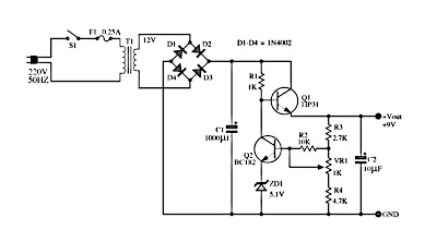 |
| Adjustable Power Supply with transistor circuit |
Power Supply With transistor circuit is quite simple and can be made with the PCB holes, so for those who want to try to directly mempraktikannya. May the power supply circuit can be useful for readers, especially for friends who need a power supply circuit with the regulator transistor.
Subscribe to:
Posts (Atom)


